Field Lessons From a Multi-Platform Solar Portfolio
Key Takeaways
- •Each solar mounting platform demands a different controlling engineering discipline be engaged before PV module layout can begin.
- •Rooftop system feasibility is typically determined by residual structural capacity and fire-code access requirements rather than available solar resource.
- •Ground-mount projects require geotechnical investigations under the 2024 IBC to drive foundation selection, making civil design a prerequisite to electrical layout.
- •Carport installations require simultaneous coordination across structural, civil, and accessibility engineering to preserve ADA-compliant stalls and vehicle clearances in working parking lots.
- •Recognizing platform-specific governing requirements at the outset of project planning helps teams avoid costly late-stage redesigns and schedule delays.
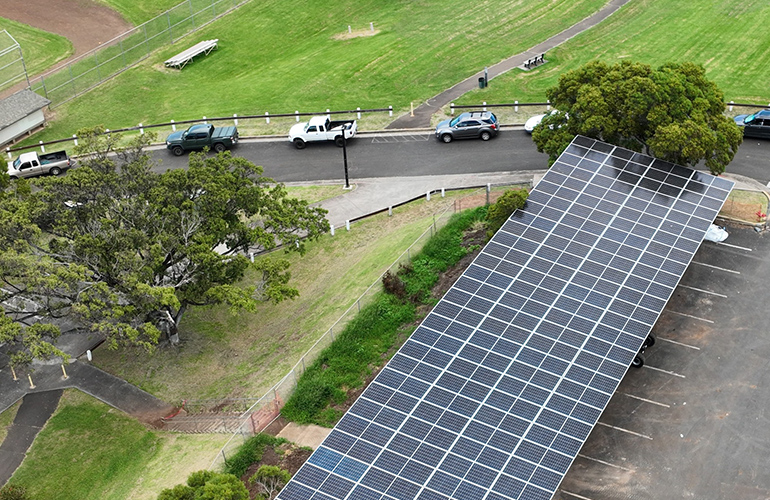
In commercial and industrial (C&I) solar PV work, the mounting surface is rarely chosen by the engineer. Geometry, land availability, shading, and budget all factor into that decision, and the design team inherits the outcome. As the C&I solar segment has grown, developers increasingly encounter sites where multiple platforms must coexist within a single project or portfolio, making it essential to understand how each mounting type reshapes the design process before a single module is ever placed.
Consider designing across a portfolio of rooftop, traditional ground-mount, and carport systems situated side by side. Each of these platforms presents its own distinct engineering challenge — and that challenge exists just as much for any one foundation taken on its own.
The platform defines the problem; it is not merely a matter of mounting hardware. Roof, ground, and carport systems each answer to a different controlling engineering discipline, different fire and electrical codes, and each requires a different engineer to be engaged before PV design even begins. The modules and racking on top may appear identical from one platform to the next, but the engineering beneath them does not.
Rooftop Systems: A Structural Problem First
On a rooftop, the array attaches to a structure that already exists and is occupied by people. Modules, framing, and ballasts represent dead load added to a building that was very likely never designed to host a rooftop generator. This is particularly common in older building stock constructed before solar adoption accelerated. These loads must be checked against the roof's residual capacity under the full load combinations of the American Society of Civil Engineers standard (ASCE 7-22), not against the limits listed in a racking catalog.
The attachment method involves its own tradeoffs. Mechanical attachment introduces roof penetrations, uplift anchorage, and waterproofing detailing requirements, while ballast avoids penetrations but adds dead load and seismic demand that the roof may not have to spare. Where structural capacity is marginal, the structural finding — not the solar resource — sets the ceiling on system size. This means roof-condition assessments and structural analyses often determine project feasibility before energy modeling becomes relevant.
The roof is also a surface where people work and where firefighters operate, and both activities demand space. Under the 2024 International Fire Code (IFC), fire-access rules remove usable roof area before any module is placed. A clear perimeter pathway is required — 6 ft at the edge, reducible to 4 ft under defined conditions — along with interior access paths and smoke-ventilation gaps between array sections (§1205.3).
This explains why two roofs of identical area can produce very different system sizes, and why the rooftop carries the heaviest fire-layout burden among the three platforms. Work at heights of 6 ft or more also triggers fall protection under OSHA standards CFR 1926.501 and 1926.502, meaning guardrails, anchor points, and walking routes must be part of the design, not field decisions.
The electrical scope is similarly constrained. Because the array sits on the building, it is subject to rapid-shutdown provisions that quickly de-energize PV conductors for firefighter safety (2023 National Electrical Code, NEC §690.12). Across buildings of varying ages and construction types, no two roofs present the same combination of these constraints, so the rooftop standard must be a repeatable method rather than a fixed layout.
Ground-Mount Systems: A Geotechnical and Civil Process
Off the roof, the governing discipline shifts from structural to civil and geotechnical engineering. The array no longer borrows capacity from an existing structure; it builds its own. The choice of foundation is a conclusion drawn from soil conditions, not a selection from a racking catalog. Driven piles, ground screws, helical piles, and ballasted footings each respond to different soil strength, frost depth, groundwater, corrosiveness, and uplift conditions. This is why the geotechnical investigation required under the International Building Code (2024 IBC, Chapter 18) precedes — rather than follows — the electrical layout.
The site itself becomes an engineering problem in a way a roof never is. Grading, access roads, trenching, and equipment pads redirect drainage across the array, so civil design leads and PV layout follows. Fire constraints shift as well. With no roof surface for firefighters to access, the code turns to the perimeter, requiring a brush-free zone around the array (2024 IFC §1205.5.1). This consumes land and converts fire safety into an ongoing vegetation management obligation rather than a one-time plan review item.
Carport Systems: The Most Interdisciplinary Challenge
A carport is often the most interdisciplinary of the three platforms because it is not simply an elevated ground-mount. It is a new occupied structure placed in a working parking lot, positioned above vehicles and people. This places two engineers in critical roles simultaneously: a carport structural engineer sizing the canopy for dead load, wind uplift, and seismic demand under ASCE 7-22, and a civil or architectural engineer responsible for protecting everything the canopy lands on. Because carports create new vertical structure in a previously open lot, the coordination burden extends beyond solar engineering into site planning and traffic flow.
The parking lot presents the same geotechnical conditions as any ground structure, but the harder constraints are found at grade level. Accessibility typically governs the layout. Under the 2010 Americans with Disabilities Act Standards for Accessible Design, accessible stalls and access aisles — their widths, slopes, and clearances — must be preserved when canopy columns and beams are introduced. Required vehicle and van clearances are easily violated when a canopy beam, hung conduit, or gutter is not coordinated with the parking geometry from the earliest sketches.
Columns cannot be placed in accessible aisles, fire lanes, drainage paths, or over buried utilities. Vehicle-impact protection must be engineered into the design, typically taking the form of a raised concrete pier at each column base, with bollards added where inverters or disconnects are mounted on columns. This provides structural protection for the load path that carries the array. Fire coordination shifts accordingly — away from roof pathways and toward fire-apparatus circulation and site access across the lot.
Common Obligations Across All Platforms
Each platform brings a distinct set of problems. A roof array is primarily a structural problem; a ground array is a geotechnical and civil problem; a carport is a structural, civil, and accessibility problem simultaneously. The engineering disciplines change, the governing codes change, and the engineer who must be satisfied first changes with them.
What remains constant is the underlying obligation: on every platform, the array must be structurally sound, code-compliant, and safe for the people around it. The practical lesson is not that any one of these platforms is inherently difficult — the industry designs all three well — but that the mounting surface silently determines which problems must be solved to meet that obligation before PV design begins. Recognizing this early in project planning helps teams avoid costly redesigns and schedule delays when a platform-specific constraint surfaces late.
Understanding each platform's governing requirements at the outset is what enables efficient engineering. It means engaging the right disciplines first and letting the real constraints drive the layout from the very start. That understanding, more than the array itself, is what distinguishes the platforms.
Archit Patnaik, PE, PMP, NABCEP PVIP, is a senior project manager at Pure Power Engineering, where he leads electrical engineering for commercial and industrial (C&I) solar PV systems, including rooftop, ground-mount, and carport installations. His work spans design oversight and project execution for developers, EPCs, and asset owners.
